pi = New pigpio
Call pi.gpioInitialise()
pi.Handle = pi.pigpio_start(nil, nil)
This works fine. Been using it for a while to control some motors over CAN bus via serial.
Needing to now connect an analog to digital board (ADS1115) so I can read the value of a POT to get some positional feedback. I did all the setup to turn i2c on, used i2cdetect -y 1 to find my device address which is &h48. I can also communicate with the board using command line i2cget and i2cset. I can set and read registers with it. So I know i2c is working on my Pi and I know that the board communicates with the Pi.
But in xojo when I try to open communication with the board using:
bus = 1
FileHandle = pi.i2c_open(bus, &h48,0)
FileHandle should be >0 but instead comes back with -2011. Which also doesn’t match any of the expected error codes for i2c or for the ADS1115. The ‘wish i knew’ book doesn’t have an example with this board but with a different A/D. But at this level all I’m trying to do is open the port and get a valid file handle.
If I ignore that and then make calls to write or read data, I always get -2011 as a return code. For any i2c method that I use. I’ve also tried the i2c_open with only 2 parameters and get the same return.
I feel like it might be something simple. But I’ve gone over the steps in the “wish I knew” book several times and can’t see anything that I’m missing.
Oh side note - I don’t quite understand the protocol on the ADS1115 so even with the set and get command line commands I’m still not getting valid data back for the position of the POT. But one problem at a time. Gotta talk to the board with xojo before working out the protocol.
Hello Michael,
The error -2011 is not typical. From what I can tell, error -2000 has something to do with the header, and the sub-error is -11, which has the description: PI_BAD_TIMETYPE, -11, //TImeType no 0-1. Someone on the Adafruit forum mentioned the ADS1115 has a communication rate of 9600 baud.
Here is the link for the ADS1115 datasheet from Texas Instruments (https://www.ti.com/lit/ds/symlink/ads1115.pdf).
Glad to see that you have I2C enabled on the Raspberry Pi, as I often make this mistake when switching between boards 
On these boards, I often search for working python code and then convert it to Xojo.
Thanks for the info. I tried 9600 same error message.
I looked at the data sheet and the library in arduino. Python code is a little harder for me to figure out. I already wasted more than a day on this. I’m going to switch to the MCP3008 and go that route since there’s sample code for this also. Should be easier to get it working.
1 Like
I’m just putting this here in case any of it is helpful: -
The ADS1115 I2C bus will definitely work at 100kHz.
Below is part of my circuit: -
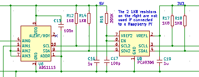
Don’t worry about the level translator IC and the 1K8 resistors can be higher. They were only this low as I was going to test the I2C bus at 400kHz but never did in the end.
I am using just 2 single ended analogue inputs AIN0 & AIN1.
This code used WiringPi, which has been deprecated, but might still be useful.
Below is my initialisation code: -
// Setup I2C ADS1115 A/D for Vibration Sensor signals
I2CHandleVib = GPIO.I2CSetup(kI2C_ADS1115_Adr) // Check if ADS1115 chip is present
If I2CHandleVib = -1 then
  I2CInitFailed = True // NOT present so set error flag
Else
  I2CInitFailed = False // Present so configure ADS1115
  // ADS1115 Configuration data (Note: High and Low byte are reversed
  // B1-0   =  11: Comparator ALERT/RDY DISABLED
  // B2     =   0: Don't latch comparator
  // B3     =   0: Comparator is active LOW
  // B4     =   0: Comparator is set to traditional mode
  // B7-5   = 001: Sample rate is 16 sps
  // B8     =   0: Mode is continuous conversion
  // B11-9  = 000: FSR is +/- 6.144V which gives a resolution of 187.5uV
  // B11-9  = 001: FSR is +/- 4.096V which gives a resolution of 125uV
  // B14-12 = 101: Input multiplexer AINp is set to channel 1 & AINn is set to GND
  // B15    =   0: Operational status
  //ADS1115_Result = GPIO.I2CWriteReg16(I2CHandleVib,&h1,kADS1115_Config_Vibration_6_144V) // Write 16 bit Configuration data into ADS1115. Set for reading Vibration Sensor signal.
End
The kI2C_ADS1115_Adr value is &h48.
Code accessing ADS1115. Please note that there is more code in the following than you would need but hopefully it is of help: -
//---------------
// VIBRATION DATA
//---------------
// VDD is +5V
// Selected FSR is 6.144V which has a resolution of 6.144 / 32768 = 187.5uV. Note that only readings up to VDD (5V) are valid
//------------------------
// VIBRATION SENSOR STATUS
//------------------------
// First voltage reading is actual voltage & second reading is the voltage being read by the ADS1115
// Sensor Short Circuit < 0.5V (0.063V) ADS115 value = 336 (&h150)
// Sensor Open Circuit > 20V (2.53V) ADS1115 value = 13493 (&h34B5)
// Sensor OK = Anywhere in between the Short & Open Circuit values
//
If I2CInitFailed = False then // Check that I2C bus is OK
  // Write to address pointer (Point to conversion register)
  ADS1115_Result = GPIO.I2CWriteReg8(I2CHandleVib,&h0,&h0)
  // Read the 16 bit conversion value (Vibration data). Note that the HIGH and LOW bytes are around the wrong way
  ADS1115_Result = GPIO.I2CReadReg16(I2CHandleVib,&h0)
  // Check for ERROR
  if ADS1115_Result = &hFFFF then
    VibrationLive =  0 // Make reading 0 if error detected
  Else
    // Result OK.
    // Swap the HIGH and LOW bytes
    Var mb as new MemoryBlock( 2 ) // Create memory areq to hold Vibration analogue result
    mb.UInt16Value( 0 ) = ADS1115_Result // Get 16 bit result
    mb.LittleEndian = not mb.LittleEndian // Swap byte order
    ADS1115_Result = mb.UInt16Value( 0 ) // Save resul
    ADS1115_Result = ADS1115_Result - VibrationCaliValue // Subtract result DC offset value from LTC1968
    ADS1115_Result = Bitwise.ShiftRight(ADS1115_Result, 1) // Convert reading back to normal as filter has gain of 2
    //if ADS1115_Result < 7 Then ADS1115_Result = 0 // If result is negative then make it zero
    If ADS1115_Result > &H7FF0 Or ADS1115_Result < 13 then
      VibrationLive = 0 // Clear the Live Vibration value
    else
      VibrationLive =  ADS1115_Result * 0.0001875 // Convert the reading back to its analogue value ((6.144V / 32768) x Count)
      VibrationLive = VibrationLive / 0.0102 // Divide volts by 10.2 mV (m/s²)
    End
    // Check if Vibration Units are mm/s
    If ButtonTestUnits = False Then
      If ActualRPM = 0 then // Check if speed is zero
        // Speed is zero
        VibrationLive = 0
      Else
        // Speed NOT zero
        VibrationLive = (VibrationLive / (6.283185307179586476925286766559 * ActualRPM)) * 60000 // Convert to mm/s
      End
    End
    If ADS1115_Result > &hfff0 Then VibrationLive = 0
    If VibrationLive > 99.99 then VibrationLive = 99.99
  End
1 Like
Wiring pi for Raspberry PI actually has alive fork in good condition.
I would use Wiring Pi over anything else any day. Reason for it is that if you want to later go on other board (or maybe right away) then almost all the makers of other boards have Wiring PI forks and not something else.
Hi Björn,
Many thanks for the links. Very useful.
SO I gave up on the i2c and instead with with the exact sample that is in the “wish I knew” book. I got an MCP3008 (MISO/MOSI) and am following example 20-3 from the book.
When I run the sample code on the pi it crashes.
The line adc1 = pi.spi_open(0, 50000, 0) //CE0 opens the spi and should return >=0. But instead it’s returning -2011. Weird because this is the exact same error code I was getting above with i2c.
I’m THOUGHT my pigpio library is installed correctly because I’ve been communicating using the serial ports on the gpio. Also when I had that i2c board hooked up I could talk to it via the command line.
But now that I think about it the serial connection that I’m using which happens to be on the GPIO pins, isn’t using the pigpio library. It’s just a serial device.
When I initialize the pigpio library using this:
pi = New pigpio
Call pi.gpioInitialise()
pi.Handle = pi.pigpio_start(nil, nil)
it is returning -2003
The pigpio_start method is using this library: pigpio_start Lib "libpigpiod_if2.so"
So how do I verify that I have that library installed? Or anyone have any other ideas?
Hi Michael,
Give me 30 minutes, and I’ll wire up the MCP 3008 and see if I get an issue.
I am using Windows 11, Raspberry Pi 4b.
Hi Michael,
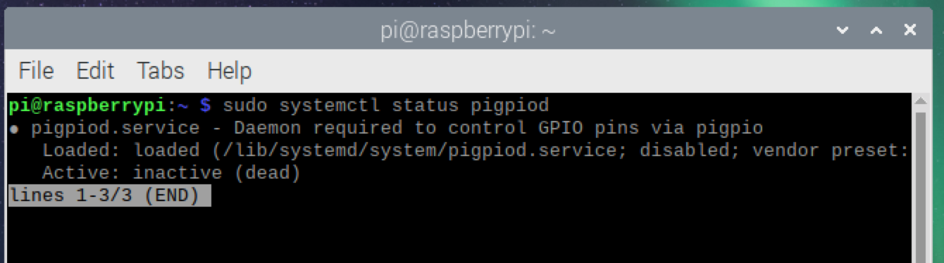
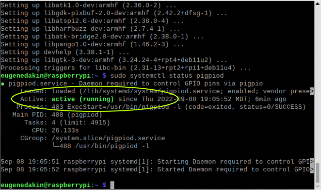
I just tried the example and it works on my Raspberry pi. Lets go through some steps to see if the Raspberry Pi might have had an issue. Type the following in a Terminal to see the status of pigpio:
The status should show 'active (running), see the below screen grab
Edit: there is a quick start guide on page 29 of the book, and we will be going through this.
Well that’s something…
I REALLY appreciate you taking the time to help me. I thought I had already done all the setup but I’ll relook at page 29 and see if i can figure it out.
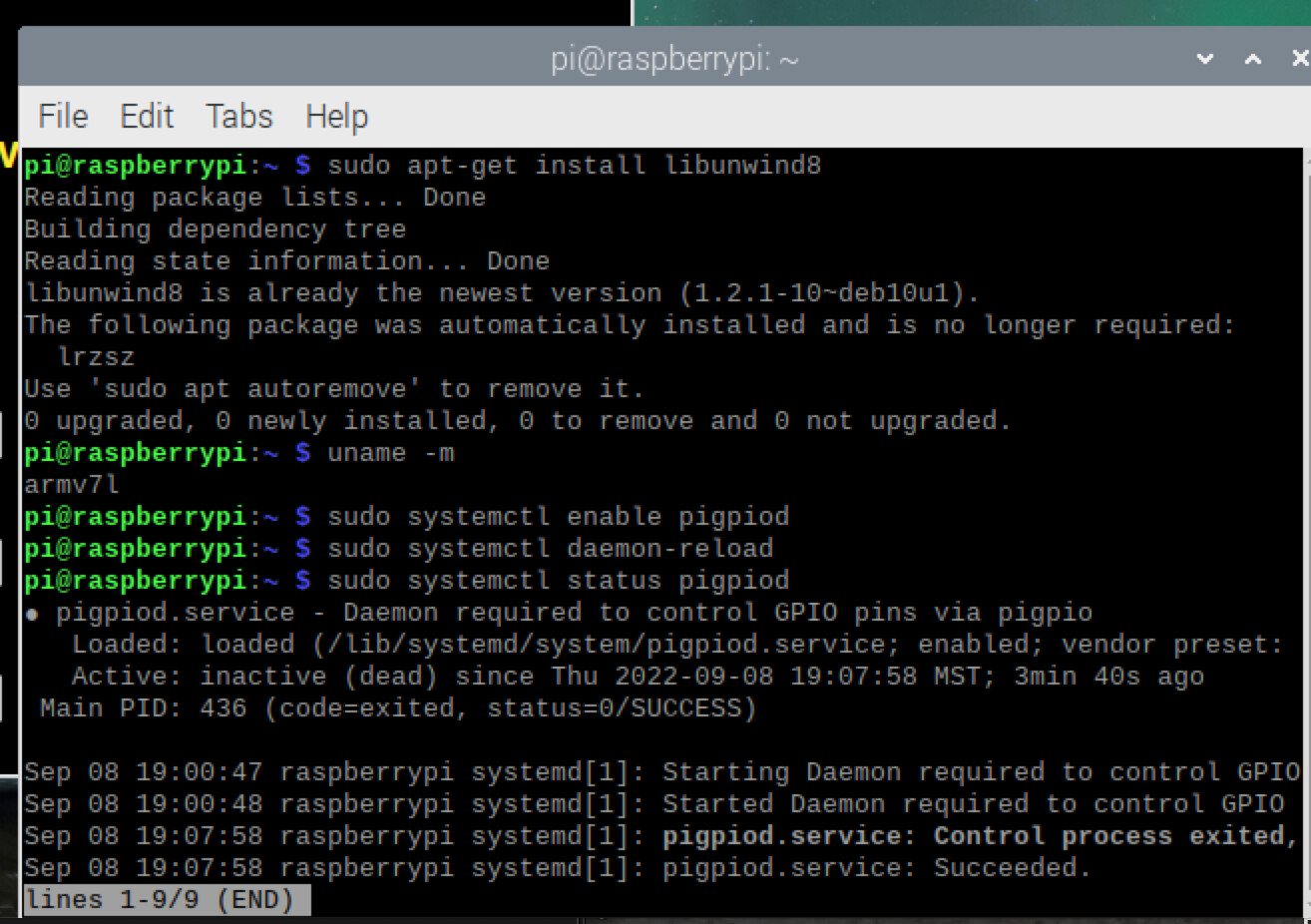
• Run the command ‘sudo systemctl enable pigpiod’ to start the daemon after rebooting
Does this have to be done every time it’s rebooted?
I followed the steps on page 29 and yet it’s still saying inactive (dead)
The daemon is a program that runs in the background, which means that when it is enabled, it will always run in the background after a reboot.
I see you’re repling but I rebooted again and now it says active.
I’m going to try my app again and see if it’s working now. I’ll give you an update in a min.
Ok, lets try a few commands, and let me know if they work for you:
Lets check to make sure that the Raspberry Pi operating system is 32-bit. Open a terminal and type
To start pigpiod server:
ok interesting… it sayd active for a min. then when I remote debugged the app it still gave me the error code. I checked again and it said inactive.
Look at this…
If the start command has been used too often, the Raspberry Pi can become confused.
Maybe try and disable the pigpiod first, reboot and then check the status before enabling
I’ll try that next. But here is an experiment I just ran.
I rebooted. Checked - Active
I launched the Remote Debugger Tool. Checked - Active
I remote ran my app. Error codes. Checked - Inactive
So the app is making it stop. That was my app which uses your example 20-3 code. I also tried it with your example 20-3 and ran it remotely. It does the same thing except that instead of stopping at the error codes it crashes.
So for sure it is the app or the remote running that is causing it to become inactive.
Michael,
This can become confusing once you run a Xojo pigpiod program. There can be only one instance controlling the server. When pigpiod is initially setup (a Xojo program has not run yet), then the Xojo program must stop the system pigpiod and restart it as a Xojo pigpiod.
If you run Example5-2 (blink LED), in a terminal, there should be a command that says
This means it turned off the system server, and started a Xojo pigpiod server. This means its running correctly