Need help XoJo help, or Trigonometry help? Ha ha

I am trying to figure out how to draw an arc with a constant radius.

I have been Googling for days, I have been watching Trigonometry videos, and tried a few AI bots. But I must not be smart enough. I have tried ovals, and CurveShapes, I just can’t get them to do what I want.

I want it to always start at the center of rectA and ends at the center of rectB

There are already x,y points for the center’s, and they change, because both boxes are draggable.

I have created a small project so someone that can help, can maybe show me.

Here is a link to download the example program because I don’t know how to include the project here.

Project Example

Looks like GraphicsPath is what you are looking for.

Thank you for responding. I have tried it in various past attempts. But I still don’t get the math right. I have tried it with AddArc, and various AddCurves. One example I draw it with one, but I can’t get the curve to have a constant radius. It looks lopsided then you move one or the other end around. I have at one time drawn it with a circle that drew over the area I didn’t want. But it just seems that it is something pretty simple that I just am not getting. I probably just need to keep looking at the math. Maybe if I extend 90° lines up from the 2 rects to make better curve points? I was just hoping that someone would just say, I do that all the time. Here is how its done. :slight_smile: I work on something pretty hard before I ask for help. But am as they say… Over this. haha

I’m not quite clear what you’re trying to accomplish. Can you take your screenshot into a paint program and roughly sketch in what you want? Annotations for Rect A, etc would be welcome as well.

I want the Blue arc to go from one end of the line to the other with a constant Radius. (Not a curve that is not circular.) I have dozens of tries like that. ha ha.

The rectA and rectB are just there to allow dragging of the line ends for testing.

The statement…

 g.DrawLine( startPointx, startPointy , endPointx  , endPointy) 

Actually has the need points in it.

What you need is Trigonometry.
An arc is defined by four parameters: centre, radius, start angle, and end angle (or alternatively the arc angle).

Given:
the centre in C with coordinates Cx, Cy
start point A(Ax, Ay)

the start angle a1 is Atan(sin/cos).

If you only have the centre C and the start point, you can find the other values very easily.
radius = distance between C and A

// find radius
var dx as double = Ax - Cx
var dy as double = Ay - Cy
var radius as Double = Sqrt(dx*dx + dy*dy) 
// find start angle
var a1 as Double = Atan2(dy, dx)
// problem: the Cartesian plane in regular Math has the Y positive upwards, 
// whereas the Xojo canvas has Y positive downwards, 
// so you either invert the sin values before calculating the angle (I normally do this) or 
// you invert all y coordinates after, i.e. Ay = canvas.height - Ay

// find the end angle
// since you want a half circle and the arc angle is Pi, you only need to calculate a new Atan with inverted dx, dy
var a2 as Double = Atan2(-dy, -dx)

// use xojo GraphicsPath to draw an arc
3 Likes

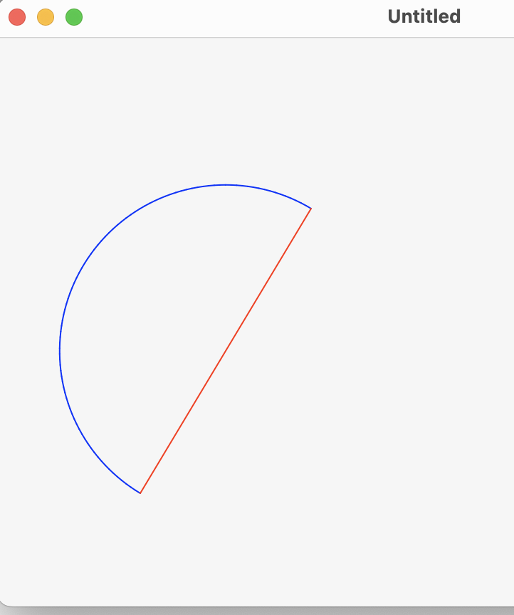
You should check out ArcShape. This Object2D can be created. When put in the Paint event of a Canvas, it will show up on that canvas when the Paint event occurs.

I have written a simple Desktop project to illustrate how this is done.
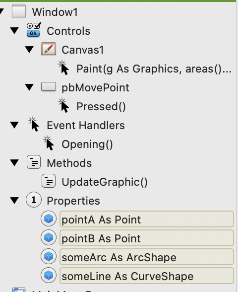
The Opening event:

Self.someArc = New ArcShape // property of window
Self.someLine = New CurveShape // property of window

Self.pointA = New Point // property of window
Self.pointB = New Point // property of window
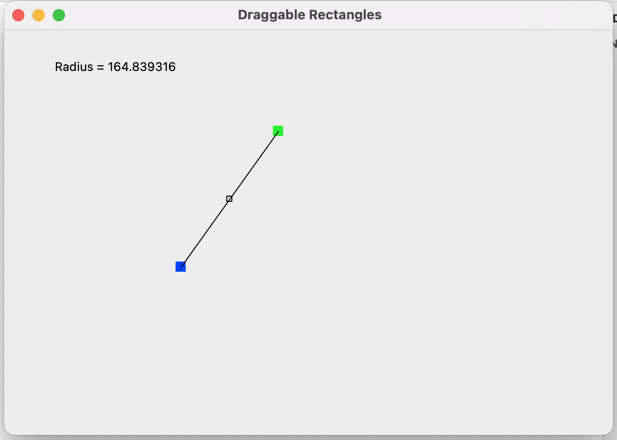
pointA.X = 80
pointA.Y = 300

pointB.X = 200
pointB.Y = 100

Self.UpdateGraphic

Window Method __ UpdateGraphic:

Const PI As Double = 3.1416

Var theAngle As Double
theAngle = ATan((pointB.Y - pointA.Y) / (pointB.X - pointA.X)) + PI
someArc.StartAngle = theAngle
someArc.ArcAngle = PI // half a circle in radians
someArc.BorderColor = Color.Blue
someArc.BorderOpacity = 100
someArc.BorderWidth = 1
someArc.FillOpacity = 0
someArc.X = (pointA.X + pointB.X) / 2
someArc.Y = (pointA.Y + pointB.Y) / 2
someArc.Width = pointA.DistanceTo(pointB) // Width and Height should be equal if want perfect circle arc.
someArc.Height = pointA.DistanceTo(pointB)

// line connecting the two points.
someLine.X = pointA.X
someLine.Y = pointA.Y
someLine.X2 = pointB.X
someLine.Y2 = pointB.Y
someArc.ArcAngle = 3.14
someLine.BorderColor = Color.Red
someLine.BorderOpacity = 100
someLine.BorderWidth = 1
someLine.FillOpacity = 0

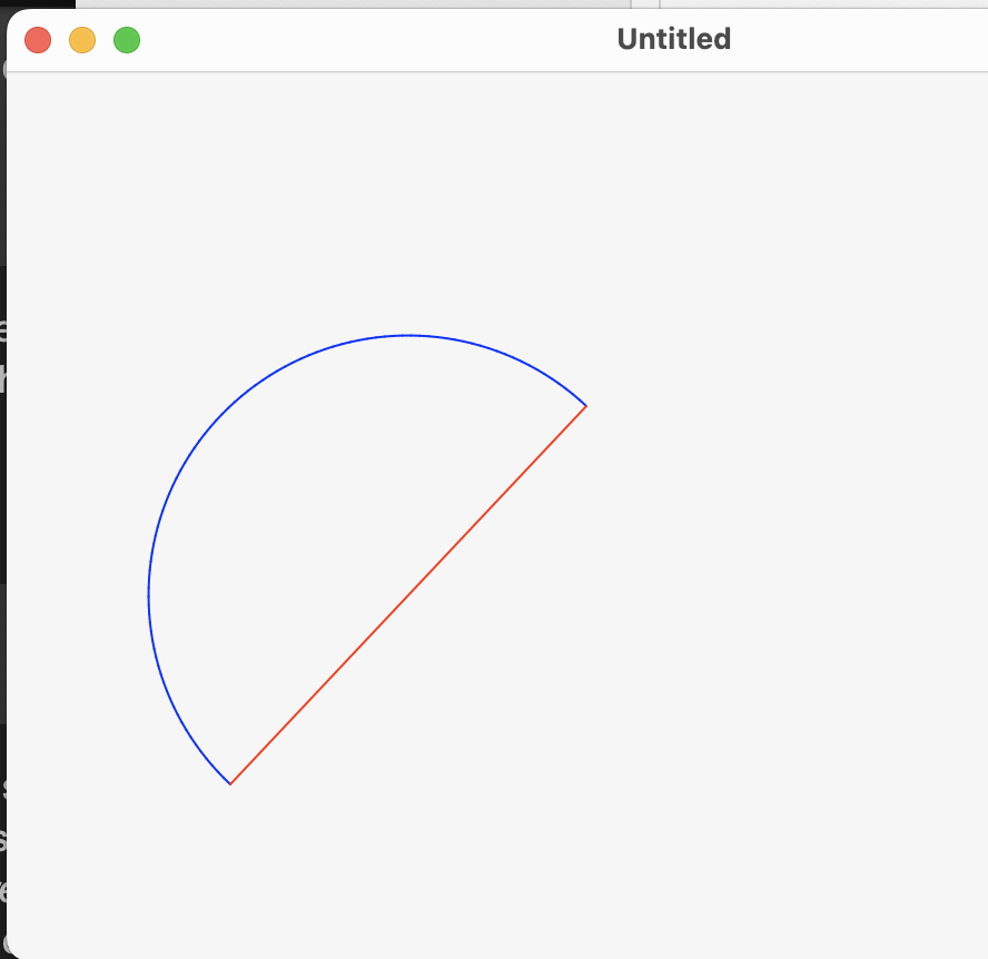
The only trigonometry requires is getting the StartAngle. This is derived from the arctangent of the line connecting the two points with a horizontal line. The example code using this in the UpdateGraphic method.

The Paint event of the canvas is simple:

g.DrawObject(Self.someArc)
g.DrawObject(Self.someLine) // line between the two points

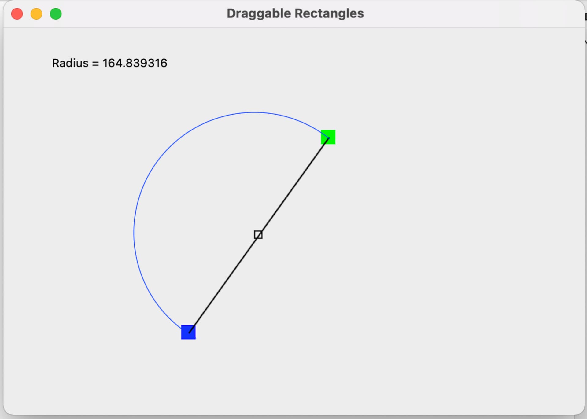
The code of the Push Button is provided to see how the graphic is updated when you change the (move) one of the Points. In this case the pointB position (X & Y value) is changed, The code here is placed in the Pressed event of the PushButton. Of course, in your case, the point position is being changed my dragging so this code would have to placed in the appropriate location to get the desired effect.

pointB.X = pointB.X + 40
pointB.Y = pointB.Y + 30

Self.UpdateGraphic

// Show the change
Self.Canvas1.Refresh(False)

If you play with this code, I believe you will be able to figure out what you need.

pointA and pointB are just the centers of the two small rectangles that you have in your diagram. It is not hard to add these graphics to you canvas. (see: RectShape)

After clicking on the pbMovePoint button.

Thank you so, so, much. This has been an issue that I have struggled with for literally months.

I found so many work arounds, that I would forget about it for weeks then come back and work on it. (That happened over and over.)

I might have been close a few times but probably had one x,or y, in the wrong place. :slight_smile:

I appreciate your taking the time to help out.

This is the project and code that I finally got to work based on your help.

Working Demo Project

2 Likes

Thank you Robert !!! Now that I know the general idea, and have it working. I will go back and play around with the code snippets you set. I have really struggled with this. As I wrote to Andrea, I have probably over the past year been close but never made it work right. (We all know what we know :slight_smile: ) So its nice to get support form people that understand something you don’t and are willing to share their knowledge. As I did under Andrea’s post, below is what I ended up with just incase anyone sees something I am dodging wrong. (Its still a draft.)

Thank you again.

Working Test File

hello,
I still have an ARC shape test
draw an arc and more
with sliding controller

https://www.dropbox.com/scl/fi/n1kl61ndrqsysov3aocln/Arc-dia-test-shape-API2.xojo_binary_project?rlkey=65u70w6v09y5snfa3qbtaa9b6&dl=1

1 Like

Thanks for the contribution, there are some cool effects here so I will explore the code further. It is fun to see how others grapple with visualization techniques.

The language is German for anyone who might want to translate this and that into English when looking at the interface or code.