Modbus and Xojo

For some time now I’ve been working on a motion picture film scanner. The motors, lights and sensors are controlled by a Teknic Clearcore microcontroller. Last year I hired a developer to write the firmware for this. It worked reasonably well in initial testing, but we had to shelve the project for most of this year for unrelated reasons. I got back into it about a month ago, found some bugs, and when I contacted the developer I found out he’s seriously ill and unable to work on it anymore. I had someone else, already familiar with the ClearCore and the motors we’re using (also made by Teknic), take a look at the code. He can get us limping along, but his suggestion (and I tend to agree) is to rewrite it because there are some fundamental issues with the current setup.

Some of what had been done by the first developer is a bit buggy, and in some cases he determined it was best to do some multi-step functions on the ClearCore then report results back to me. Unfortunately, the code is a bit of a mess, and the setup we used involved two TCP channels: a server on my desktop app to receive unsolicited alarms and errors from the ClearCore and a server on the ClearCore to receive commands from my application. This has proved to be …clunky at best.

The new guy suggests a completely different way of approaching this: A single TCP connection to the ClearCore, using modbus. He would create a series of registers that store pertinent data (motor postions, motor states, LED states, sensor states, alarms, etc). I would poll this frequently from the desktop to see if there are changes. Certain critical functions are handled automatically by the motors (example: if the film breaks, the motor will detect that torque is changed and will stop instantly)

With this setup, we are moving all of the logic into the desktop application, rather than having the ClearCore handle some multi-step processes. I personally prefer this, at least in principle, because I will know exactly what’s going on at any moment. But it also makes things a little more complicated for me in the front end app (rather than telling the controller “LoadFilm” I would need to send separate commands: enable the feed motor, enable the takeup motor, enable the capstan, lock the capstan, check the torque on the motors and potentially make adjustments.). Right now, I send a single command and wait for it to tell me we’re good. But the way it is now, if we need to make changes it needs to be done by the third party developer working on the firmware, which takes more time and costs money – and is difficult because it’s impossible to give that developer a duplicate machine (it weighs 500lbs).

So I am strongly inclined to try this new approach. The basic setup I’m imagining on the Xojo side would be a timer that runs very frequently (50ms maybe), and checks the clearcore for changes. All of the registers that the firmware guy exposes to me would be mirrored in my app as computed properties, so that I can react to changes in the register values when necessary. This is, in some way, similar to what I’m doing now with a few functions.

The devices being controlled by the ClearCore are:

  1. Feed Motor
  2. Takeup Motor
  3. Capstan Motor
  4. Camera Stage Stepper Motor
  5. Lens Stage Stepper Motor
  6. LED R-R-G-B-IR channels (5 channels total)
  7. Camera Stage front and rear limit sensors
  8. Lens Stage front and rear limit sensors

I guess my questions are:

  1. Is it feasible to run a timer at a frequency of 50ms? Can I go faster than that?
  2. Are there any obvious issues I might need to be aware of with a setup like this?
  3. In doing an operation like homing the camera stage (a linear stage controlled by a stepper, with a hall effect limit switch), I need to react immediately to stop the motor when the limit switch is triggered, because if I don’t the motor could send the stage too far. This works fine right now when done in the microcontroller, but I’m concerned that latency might be an issue doing this in a modbus setup.

Searching the forum, I saw there are some modbus tools available for Xojo, so we’d probably start there.
Time-sensitive mission-critical stuff like stopping a motor to prevent a mechanical crash is really best done in MCU firmware. Do what’s necessary down at that level and let Xojo handle the high-level logic.

Timers can be run at 50ms but might bog down your app depending on what’s being done in the Action event and how many such timers are running. Xojo timers are not very accurate, so some trial-and-error might be necessary. MBS make a vague claim that their timer is more accurate at small periods, but no quantitative info is given.

4 Likes

Thanks. So in terms of the danger of something catastrophic happening, it’s pretty much not a major issue. With the example I gave, with the camera and lens stages, maybe if we just slow those motors down enough it will buy time to react when the hall switches are tripped. They’re already quite slow. But I will ask the developer what would be involved with re-using some of the code we already have to do it in the firmware. These motors are used only when setting up at the beginning of a session, so if this is a bit slower, it’s not a big deal.

For the main film transport, the motion is mostly in small increments - we tell the capstan motor how many steps to move and in what direction, and we mostly only move one frame at a time. This is not a fast machine - The camera, at top resolution, is limited to about 3.6 frames per second. For a color image, where we’re capturing three exposures, it’s going to be about 1 frame per second - so we’re not doing a lot of coordination of simultaneous events, it’s all sequential and nothing happens until we know the previous step in a given process is complete.

The Teknic motors are very cool. They have their own firmware and configuration software, so we can specify things like under what circumstances to shut down. If the film breaks or runs out, the motor can react in milliseconds to the sudden change in speed and will shut itself off and set an alarm state. It happens so fast, you don’t even see the motor appear to speed up. It’s pretty impressive. That moves a lot of the really critical stuff out of the MCU even, directly onto the motor. Things like speed ramps are handled in the motor as well, all pre-defined and configurable. So all we really need to do is tell it to go to X position and then check to see if we’re there.

I kind of pulled the 50ms number out of thin air, but we’re trying to keep the entire process of shooting a frame of color film to 1 second. In that time, we need to:

  • move the film into position
  • light up the Red light
  • shoot an image
  • turn off Red and light up green
  • shoot an image
  • turn off green and light up Blue
  • shoot an image

then we send those three off to either a helper app or another thread to be processed into a color image and displayed in the GUI. Meanwhile, we begin moving to the next frame and repeating the process. At 50ms per loop of the timer, we’re talking up to 300ms just to get the feedback back from the MCU that we’re ready for the next step. The combined capture time for the three frames (exposure and offload to the frame buffer) is about 600ms.

So it’d be tight at 50ms, putting us right at about a second, not including the time to shuttle to the next frame – that will vary depending on the size of the film. (35mm is only about an inch and a quarter but IMAX is about 3 inches).

Sounds like those smart motors will make the whole thing a lot more feasible and easier on the Xojo side.

What is the purpose of the timer? Can you not make it event-driven, so that as soon as you’re ready to move the film you tell the motor to go, and when the motor is done it tells Xojo it’s ready?

We are currently having the MCU push data to is. when data is received, computed properties on the Xojo side are updated, and in some cases these trigger further actions. The main issue is that doing this is much more complex in terms of the coding on the MCU side. We have also had issues with lost connections (say the computer has to be rebooted, then when we bring it back up it takes a minute or two for the MCU and the computer to start communicating again. on Windows. On mac, it’s a lost cause unless you also reboot the controller. It took a long time to figure out that the problem was something on the mac side. I still don’t have my head wrapped around it, but on Windows we do eventually recover the link.

The programmer I’m talking to says it will be significantly less expensive on his end if he basically just dumps the data we need into a set of registers, and allows me to update those registers. He looks for changes (say in the register showing where the motor is. If it’s different, he moves to the new position. If it’s not he stays put). On my side, I just have to grab the registers and populate my properties and I can do the same. So it comes down to the cost (I’m waiting on an estimate), but it also greatly simplifies a lot of stuff and potentially makes some capabilities possible without having to have him go back and modify code (for example: we may want to add in some relays to control fans for future use. He can simply set up some generic registers that are linked in his code to those pins, so we can turn them on and off as we need, when we need. They may not have a nice name, but we could use them in a year if we decide we need to, without having to pay him to modify things.

So we would use a timer to poll the MCU to look for changes/status/alarms/etc, and we would simply send a message via modbus TCP when we need to tell the MCU to do something

I do appreciate that he’s thinking about this kind of stuff. This is a completely different way of doing this though, so I’m still trying to wrap my head around the possible pitfalls. The biggest one I can see is the natural delays caused by using a timers to look for changes.

How do you poll the MCU? Instead of a Timer, that code might be better in a Thread.

1 Like

My thought was a timer that runs at some predefined interval in the main thread, though that would need to be tested to see if it bogs things down. But if I can do it from inside another thread that probably makes more sense.

In talking to the firmware developer last night, he suggests that we can group the register data into two or more chunks - so stuff I need more or less constant access to (things like alarms, or current speed, position and torque readings), I can call frequently. Stuff I need less frequently I can fetch every second or so, or even less depending on how we group it.

How would you do it in a thread? inside a tight loop with a delay?

Atually is a really bad idea to use a software timer to interact with a microcontroller. The OS makes its best to give you the time but it is not precise.

so, things like alarms, speed, position and torque readings that need inmediate action should be addressed in the firmware itself and never deppend on communication. (or at least implement a really tight timeout mechanis with default actions.)

Mostly you communicate to the pc just to notify the current state, errors, actions taken, etc.

Of course you should be able to modify the parameters of the microcontroller from the pc to alter the default actions.

An open channel with the MCU and the MCU sending the data sounds like the best option. Maybe is just a planning problem, you should take some time defining a communication protocol with “lost connection” handling before codding

1 Like

Again it’s not really about precision. I just needs to be several times per second. Given the speed of the PC we’re running this on, that doesn’t seem like a big ask.

The scanner runs very slowly. It is not in continuous motion, and it is not high speed. There are not lots of things happening simultaneously, it’s all sequential. We tell it to move a few inches, it does, we take the picture. Rinse, repeat. The only things that could happen that are potentially bad are if the film (or a splice in the film) breaks, or if the film runs out. And in that case, the motor stops automatically, without any need for the MCU to be involved. In cases where it is in continuous motion, we can poll its location and slow it down or speed it up as needed. For actions like moving to a fixed location, we have that location already and the MCU will handle getting it there. We just need to tell it to do so. The motor handles the speed ramps, the motor handles positioning, and it reports all that to the MCU. We just poll occasionally to update our location in the GUI.

If we were running this thing at the speed of our other film scanner (commercially purchased), which runs at up to 60 frames per second (approximately 4 feet per second for 35mm film), then we wouldn’t do it this way. Our goal is to make a functional scanner for in-house use that runs as close to the nominal speed of the camera as possible - that is, 3 frames per second at the fastest. it’s not a commercial product. It’s not for sale. So it needs to be good enough, and it needs to be reliable.

As I said above we tried this. And I spent 2 months messing around with lost connection handling which still isn’t quite there. It more or less works on Windows, it doesn’t work reliably at all on Mac. We can very easily re-establish a lost connection from the desktop to the MCU, but the other way around doesn’t seem to be so straightforward, without significant work. On the mac I can reliably get the machine into a state where we are no longer receiving alerts from the MCU. On Windows the same thing happens, but it automatically recovers within a minute or so.

We are hiring someone new only because the person who was working on this is gravely ill and can’t do any more on it. His code has some issues and it would be more expensive for a new programmer to try to understand and fix that code, or to start from scratch and re-do what was done with a custom protocol, than it would be to hire someone familiar with this particular MCU and these motors, who already has libraries of tested, re-usable code he can use to put something together quickly, that just works.

In discussing what we can do, I really don’t see any downsides to his proposed structure, other than the built in lag of timer delays in fetching information from the machine. We can send commands to it whenever we want. Getting statuses will be limited to the timer interval on the Xojo side, and those intervals might add up inside a given operation, potentially slowing down the overall speed at which the scanner can run. That’s really my only reservation.

Ouch.

Is there a handshake between the two sides? Can the Xojo side send a command and expect to get an OK or ERROR back? I would always design it like that. Then the Xojo thread can send the command, suspend itself, and have its execution resumed by the DataAvailable event handler. You can always set a timeout on the wait for data and at timeout have execution resumed for the thread, which can then try to interrogate the other side to see what is going on.

I would need to ask the developer if there’s some kind of handshake But I think the answer is probably no, based on my understanding of what he’s proposing. We’re still hashing out the specifics of how this would work as he works on a price estimate. Very little is happening on the MCU - it’s basically the intermediate between the devices/sensors and the PC. he would be handling some operations like homing, but for the main film transport a lot of the motor functionality is predefined in the motor’s firmware, updatable through the manufacturer’s software. (things like max speeds, speed ramps, shutoff thresholds, etc)

My understanding, however, is that he has about 50 registers on the MCU containing only numeric values (mostly 16bit integers, some are larger). Some of these are R/W, some are Read Only (to me). For example, if I want to move the capstan to a given position, I send a command that writes to that register. He sees it’s been changed and sends the motor there. I can tell we’ve arrived when the current position matches the target position.

The read only registers are for statuses, alerts, positions, and are updated constantly as data comes in from the motors. These would be checked frequently

We would group them logically so that I could read blocks of registers with a single command. Less frequently accessed registers we’d handle individually. For example: The camera and lens stages are only used when setting up a job. They aren’t changed while scanning because those stages remain in a fixed position. So we don’t need to fetch their position data constantly - only when setting up. Those would be grouped separately so we’re not moving/parsing more than we need to.

Does that make sense?

I take it you mean you have the Xojo side send a command to the machine that his firmware interprets as an instruction to set that register? I’d insist on a handshake so that the Xojo side can remain responsive and not get wedged; I’d do all that in a thread for the same reason. Does he ever send you unsolicited data?

Getting your data exchange protocol well-defined at this stage is crucial, IMO.

Yes. Once sent, I can verify receipt by checking the appropriate register.

Can you explain what you mean here?

No. I’m thinking of it as a kind of shared chalkboard. When I want to issue a command, I tell him what that command is, he updates the chalkboard to reflect that command and does whatever that thing is. There are other registers I can read for updates on state - where a motor is, what the current state of an LED is, if the camera or lens stage was successfully homed, etc.

Errors and alerts are reported in other registers. Each motor, for example, has a “status” register where I can get the state of the motor (enabled, disabled, fault state, etc)

There are three goals here:

  1. Simplify the communications. The two-channel setup we had before (a client and a server on the desktop and a client and a server on the MCU was too clunky and we had lots of problems with it).

  2. Hire someone to build a stable, reliable, simple system I can use to communicate with the motors/sensors/LEDs. A handful of functions that are best handled on the MCU, are done there. (homing the cam/lens stages, for example). The transport motors are self-monitoring with built-in encoders, and only work within predefined operational parameters. They will stop in a fault state, reporting that to the MCU, which I can then pick up. To move to a given position, we just tell it that position, and it goes there or faults.

  3. Move the bulk of the logic to my app, so that going forward I have complete control over what’s happening, when. This is so we don’t get into a situation like we’re in now, where someone wrote custom firmware, but is no longer able to work on it leaving us stuck having to either spend a small fortune getting someone up to speed or doing a rewrite just to get going. The existing code is problematic in spots (both bugs and structurally), so now seems like a good time to do a rewrite, but I don’t want to do that any more times than is necessary.

You mean you can read the register without that involving his firmware? And other registers too?

No. It would require his firmware. What I’m saying is that after issuing a command, I can verify that the command was received on the next check of the registers.

Are you talking about the connection between the two in general? I’d need to check with him about how that’s initiated, but modbus is a well defined and understood data communications protocol going back to the 1970s, which is why he’s suggesting it. Assuming the libraries referenced in my first post work well with Xojo, the understanding is I don’t really need to think too much about the underlying transport issues, just what/when to send and retrieve data.

More Specifically, I’m referring to this post by @Dennis_Hoskins

Yes. I don’t know about modbus, but the general principles for me would be as I described above. Use events and a thread so that your Xojo app cannot hang. If you have a tight loop then if the other end doesn’t respond then your app won’t respond to you and you’ll have to restart it. I would expect that if you send a command to set a register, then he’d set it, read it out, and send the read value back to you. Untimately if his code is then (for example) supposed to move a piece of hardware to a new location, he should also be moving it, then reading where it actually is, and sending you that, too.

What you don’t want is the Three Mile Island situation where the operators sent a command to close a valve, but the actual, real, posiition of the valve was not monitored. See also in Wikipedia about the Buncefield Fire.

Inside a loop that yields. The problem with timers is they are not accurate. A thread gives you more precise control. The general idea is you take the current Microseconds and calculate when the next action will be. Then you sleep some portion of that amount and then check how close you are and sleep some portion of the remaining time. Repeat until you’re within an appropriate threshold, then perform the action and calculate the next time.

1 Like

Ok, I have some more information from the developer after discussing. Basically - it is a 2-way protocol, so we get acknowledgement of received commands:

I don’t think Modbus is going to delay you because it really is a two way protocol. When you issue the write command to a register Modbus will responds with an error or an OK msg (Exception Codes | Simply Modbus Software). This is often the return value or exception of your library’s WriteRegister function. You could also issue a read register command to confirm the specific value but that isn’t necessary.

And he has confirmed that the response time on the MCU side is more like 0.5ms - 1.0ms from receipt of command to response so that likely won’t be slowing anything down either. So with this setup, I think I will use a timer in a few situations (such as when we’re shuttling, which could take a couple minutes, to fetch the current position for display in the GUI), but for the most part it should be command/response like we have now.

Based on our most recent conversation it doesn’t seem like I won’t have to make too many changes to what I’m already. I’ll need to replace the message parser I wrote, which was the plan all along anyway, with something simpler that deals with the all-numeric responses from the MCU, but most of the rest of the code should remain intact.

I’m planning to test this soon using the libplctag wrapper linked to in my first post, with a modbus slave simulator running on a windows machine.

So just a quick followup on this: Had to put this whole project aside for a bit while we moved to a new office. I started working on it again this week and one of the first things we need to do is make sure we can reliably get Xojo speaking modbus to the controller.

I downloaded a Modbus Slave app (basically a simulator), for testing, at the recommendation of the firmware dev we’ve hired.

On the Xojo side, I’m using libmodbus, which is a C library. I’ve built a simple project with a class that incorporates this library to handle all the communication. It’s working well so far. In fact, it’s far simpler than what we were doing before, where we had to have a whole message parsing system.

I’m only going as far as implementing Modbus TCP, but it should also work for Modbus RTU. The nice thing about this is that it’s dead simple to install on the mac, where I’m doing my testing, using homebrew, and it eliminates all TCP communications within Xojo since the library itself handles all of that, making things much simpler on my end.

Basically all I had to use to make this work for our purposes are the connection, read, write, and error handling functions. I’ll see if I need to add anything else later if it comes up but for the moment, this is all we need.

It’s very fast. My testing iMac is on our network via Wifi. The Modbus slave app is on a windows machine that lives a few rooms away in our server room connected to the 1gig network via ethernet. I have that windows machine on a KVM up on my desk, and the response time when I issue a read or write is as fast as the letters appearing right now while I type. That is to say, effectively instantaneous. I haven’t thoroughly measured the latency yet but a simple read of all the registers into an array takes 0.47ms. I can live with that.

The library handles receipt confirmation. So if the read or write operation fails, the library returns an error. If it succeeds it returns 0 (or another integer, depending on the function).

We will likely just poll the device for errors and status updates, but with libmodbus I can set up my app to listen, and the firmware developer could push errors to my app through that channel. I don’t think, given the relatively slow speeds at which we’re operating, we’ll need that. i should be able to just check the device several times per second and that will give us plenty of time to react.

1 Like

Update on this project.

We have the new firmware installed and it’s working great with modbus as the comms protocol, and the libmodbus library in Xojo as the interface to that. We made a couple modifications to the overall setup. Now, instead of one controller with an expansion board, we’re using two separate but identical controllers. This is because the controllers have a limited number of motor-specific connectors that buy a lot of functionality, vs using PWM on a generic I/O port for motor control. since we have a total of five motors in the whole system, and the controllers are only $99 each, it was kind of a no brainer. The firmware is the same on both, but there’s a jumper on one port of one controller to sets that port to High, so that the firmware knows that’s for LEDs and the cameras and lenses.

https://youtu.be/Dhb0ArCoo0U

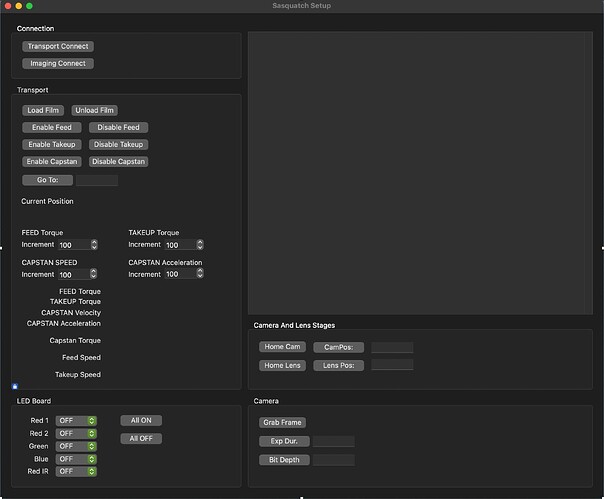
After a lot of back and forth with the motor manufacturer we got things dialed in yesterday. This video shows my software (dark UI in the background), controlling the feed and takeup motors, and the motor manufacturer’s software (the one with the scopes) generating the repeated motion. This was so we get the motor settings tuned to settle when the film is still. In the scopes, blue is the error rate, and red is the capstan motor’s velocity. So we wanted to get the blue line to be flat at the same time the capstan is not moving, and we did that yesterday.

The whole system is controlled from Xojo. The controllers use Modbus as the communications protocol and store data in a set of registers on the controller. When my software writes to specific registers, those writes trigger the controller to do something (such as moving to a new location, or turning an LED color channel on at a specific brightness). Some registers are read only, and tell me things like current motor speeds, torque levels, etc. I am currently polling the controller every 100ms to update the critical registers, which are grouped together into one bank – so, one read operation via modbus to get about 20 registers at once, and then those values are dumped into computed properties. Some of those computed properties react to the new values, some just store them.

The app you see there is a barebones testing app I whipped together in a couple hours based on code I had previously written for discrete parts of the system. The actual user-facing software will be different, but this app will evolve into the tool we use to set up the different kinds of film we’re running through the machine.

BTW, the film you see here is 10 perf IMAX, a motion picture format similar to 6x6 medium format still film, used mostly for military and scientific applications (such as the cameras around the launch gantries of the Apollo and Space Shuttle missions. Most of what we’ll run on this will be 35mm or weird archival film formats similar in size to 35mm. The whole point of this machine is to be able to scan stuff that no other scanners can.

After many years, I’m seeing some light at the end of the tunnel!

2 Likes