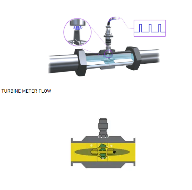
I want to use a flow meter to count the flow rate of liquid going through it. Each pulse means a fixed volume of fluid has passed through the meter, and the total pulses is the total flow that has passed through the meter. It is a turbine flow meter shown below.
The digital output is “open collector output” with a range of 0.0 volts to 35 volts. I will step the voltage down so that there is no damage to the Raspberry Pi Board.
My guess is that I have two (?) possible options:
Measure the output voltage, which is directly related to the pulses - similar to PWM, just in reverse?
Or is there another way to measure the pulses - possibly frequency with the Raspberry Pi?
I would use interrupts, each interrupt adds one to a counter, and the counter represents the volume flowing.
on a collector output, you simply have to feed it with 5v, and the output will not be more than 5v
it can support up to 35v, but using 5v will be just fine for measuring, and for the Pi inputs.
Oh, and this coud be done with a simple arduino (or esp8266 or esp32) instead of a Pi white elephant…
Are you wanting to find the total volume, or the flow rate? If you want the total volume, then simply count the pulses. For flow rate, eg., litres/second then you need to count pulses per unit time. The way we used to read these meters for flow rate depended on how fast the pulses were coming in.
For slow pulses, we measured the time between incoming pulses. Start a timer, and whenever a pulse comes in, note the time and reset the timer. The flow rate is the reciprocal of the time.
For faster pulse rates, we would use a timer set to a fixed time and count how many pulses occur in the set time period. The flow rate is then directly proportional to this count.
Depending on whether the pulses are generated electromechanically or not, you may need to add some debounce logic to your code. I suspect you won’t need to debounce the input, because a Rpi running Xojo won’t be fast enough to catch a contact bounce. But, if using an interrupt to catch the pulse, make sure to disable that input immediately in the interrupt service routine to make sure that multiple contact bounces don’t get queued. Then re-enable the input just before exiting the routine.
I think that the PI is not made for this kind of measurement. It would be better to use an arduino or other microcontroller to do the counting and then send the data to the PI
Not answering your question, but FYI if the output is open-collector there’s no need to “step down” the voltage - that’s the whole point of having an open-collector output. It will pull the Pi’s GPIO to ground, but when the state is high it will effectively be open-circuit and the input will be pulled up to the GPIO rail by the GPIO’s pullup, assuming it has one. If not, then just add a pullup resistor to the GPIO supply voltage.
Thank you @Julia_Truchsess. My thought (which could be incorrect) is to maximize the voltage range to add a decimal-point or two on the final flow rate. After your comment, you are completely correct as I can measure the voltage to a few decimal points from 0V0 to 3V3 and it will calculate out to a good value.
Yes, I am going to pull-up the GPIO to provide enough energy to run the circuit. Thanks for your helpful information
If what you’re interested in is “flow rate” represented by the frequency of the incoming pulses, and the pulses are fixed-width, then you can just add a buffer to convert the open-collector output to a push-pull output, follow that with an R-C filter to average the pulses, then read that with an A-D converter. The DC average will be proportional to the pulse rate. This scheme has the advantage of no time constraints on the Pi - it can read the voltage at any time. The product of the R and C should be ≥ 10x the longest interval between pulses to ensure a ripple-free output, I’d look at it on a 'scope to confirm.
Using an ESPxxx board is very good suggestion, it would count the pulses from the flow meter. Having the frequency of the pulses is of no help, because you need to how many of these pulses were issued.
@Eugene_Dakin , you talked about using Raspberry Pi. If we forget about the hardware used to implement the system, what do you need your system to perform ? If you need to provide an user interface and some processsing, for example needing to have a specific volume of liqiud to go through the flow meter, then using a Raspberry Pi is a good idea.
The Pi is not a good fit to count the number of pulses, but you could use an ESPxxx for that purpose, connect the ESPxxx to the Pi and query the count, and use the the »ESP xxx when the target volume is reached.
With a Pi and an ESPxxx, you can craate very powerfull system !
The flow meter is a turbine-type, where the output will look like a PWM. Each revolution of the turbine will be measured, and I am guessing something similar to a Hall-Effect sensor - but I could be wrong. At a slower flow rate, the pulse width ‘might’ be changing, as I would depend on the Hall-Effect sensor(?).
One reason for a Raspberry Pi was for the additional memory to record data points and download the data on a thumb drive. As a few of you mentioned, a ESP and Raspberry Pi would work well together for this purpose.
The amplitude of the pulses should be the same, meaning a 3V3 input would have a pulse height of 3.3 volts. If I were to measure the analogue voltage, its possible that I could create a curve to prove the flow rate - and thats getting too complicated for this application
Thanks again for all of the helpful suggestions everyone, much appreciated!!!
In these things (counters) you must “look” at the edge, rising or fall, the width of pulse doesn’t matter.
If the counter is MCU based, the width must be always the same.
Using a ESP8266 with a firmware like Tasmota would be great, you can get the “counts” by several ways in the RPi, ie MQTT. You can create a counter and read directly the count, or pulses, check it.