Yup. Appears you have all the correct links.
Sorry, I don’t have the code for this SPI connection - its close to the MCP3008, but not quite the same. If you have a little time, I’ll order it and then wire-it up and post the code. You have helped me out in the past, and it would be good to return the favour.  Let me know if this works for you.
There is no deadline on this project. This is purely a fun time project
I might try to turn it into a training video at some point, but that’s a big maybe. I still need to figure out how to do a PDI loop in Xojo too once all of the hardware is figured out.
Your Raspberry Pi programming with Xojo book has been invaluable. A lot of good information in it and highly recommended. You can quote me on that one.
Thanks for your kind words about the Pi Book!
I have ordered the parts, and it will get here in a couple of weeks, unless this happens…
Cool! I won’t get back to it for a few weeks anyway.
Canadian AAA

Hello Bob,
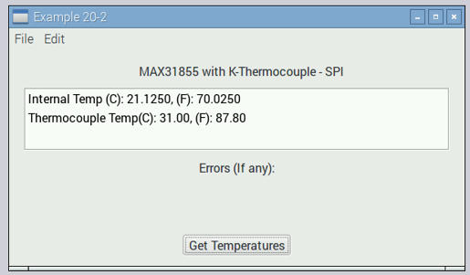
The parts just arrived and here is a screen grab of the running program:

Here is the download link for the project: Example20-2
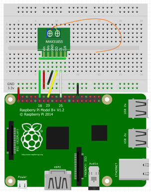
Here is how the project is wired:
Max31855: Raspberry Pi
Vin: +3.3 volts
3Vo: no connection
GND: Ground
DO: GPIO 32 (Pin 16)
CS: GPIO 25 (Pin 22)
CLK: GPIO 18 (Pin 12)
If the temperature reading of the thermocouple is decreasing when the thermocouple has been warmed, then reverse the connection of the thermocouple to the MAX31855. LOL, learned this the hard way.
Happy to help!
ohhhh…awesome. New toys to play with this weekend!
I’ll let you know how it goes.
[quote=278566:@Eugene Dakin]Vin: +3.3 volts
3Vo: no connection
GND: Ground
DO: GPIO 32 (Pin 16)
CS: GPIO 25 (Pin 22)
CLK: GPIO 18 (Pin 12)[/quote]
Finally got back to this. I’m assuming you meant GPIO 23 instead of 32 above since Pin16 is GPIO 23 and that’s what the example app is using.
I’m starting to wonder if I have a bad board because I’ve verified wiring and that outputs and inputs are working as expected. When I run I get nothing but zero’s and no error messages.
I accidentally hooked +3.3 volts to 3Vo and got all 1’s so at least I got something by accident.
Any ideas on what to try next?
Hi Bob,
Yes, your right, It should have been GPIO 23. Here is a clearer breadboard layout. My apologies.
Vin: +3.3 volts
3Vo: no connection
GND: Ground
DO: GPIO 23 (Pin 16)
CS: GPIO 25 (Pin 22)
CLK: GPIO 18 (Pin 12)
I just wired up the example and ran ./Example20-2 and it works.
Here are some addition values (version?) that are on the backside of the 38155 board:
CC-2 94Y-0 v2 1606
Added Comment: something that I did notice, is that the 12-bit internal temperature was off by 1-bit. After adjusting the bit then I was able to get the correct temperature.
Hi Bob,
I went into more details and added this to the book. Here is the link to download this example:
If the temperature values are not quite right, then I can modify the existing code to read the binary values the MAX31855 is sending.
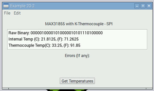
Here is modified Xojo Example 20-2a, which shows the raw binary from the MAX31855:
The following screen grab shows the raw binary data with this example:
Does your Raspberry Pi get something like this?
Slightly warming the internal temperature of the chip with the touch of a warm finger should increase the internal temperature/binary reading. If a reading is taken with the finger physically touching the chip (and circuits) the temperature will not be correct because a finger conducts electricity which is read by the sensitive MAX31855. 
It’s reading nothing but zero’s. I have another chip on order so hopefully it’s just a bad chip.
Yes, there should be some type of returned digital information other than zeros. Agreed, I also hope its just a bad chip.
Success! Bad thermocouple board. Wow. That was a painful experience.
Now on to the next problem of doing the PID Loop. Any words of wisdom?
Glad that it is working!
Yes there are a few tips (and I might be missing a few):
- the PID loop is usually quite slow, usually a temperature reading of once every 1 to 10 seconds is good for an oven.
- Once the oven is getting close to the desired temperature, start slowing down the added heat. If overshooting the target temperature is not a concern, then this is likely not an issue.
- Always have safety shutdowns, both through the program and manually. When I am engineering a heating device, there is a safety shutdown that is independent to the Raspberry Pi. Lets say the Raspberry Pi program has an internal exception and is stuck with power going to the heater, then there needs to be a safety shutdown that is separate and will turn off the power to the heater. Test the safety shutdown to make sure it works as expected.
- Because I am a geek, I like to have a graph of how fast the oven warms up and cools down - but thats just me

- Double check the temperature that the Raspberry Pi is reading is the same as with a manual thermometer that you know is accurate. Sometimes the temperature can be out by alot - calibration is your friend
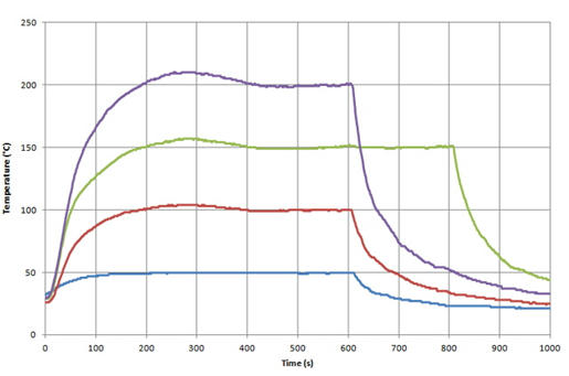
A typical calibrated heating curve with a minimal temperature overshoot may look something like this:
Lets say that the oven target temperature is 200 C (purple curve), the rate at which the burners are starting to cut back at around 130 C. There is an overshoot of about 5-10% in the purple line and the temperature reaches equilibrium at about 400 seconds.
Glad the new thermocouple board works ![]()
Right. I worked in the steel industry for a number of years. Actually looking for an actual PID loop that’s tunable if I can get it.


