The whole pin numbering on the Pi makes my brain hurt. Example: GPIO 1 can be set manually on and off by gpio write 1 and gpio write 1 respectively from the command line. In my Xojo app I use 18 as the address. And this works all day long from both my Xojo app and the command line.
Here’s my gpio readall listing:

So GPIO1, to me, looks like it should be pin 12 but it is BCM 18.
And here’s my actual wiring that works which is pin 18.

WTF. Really? Lots of different numbers and they just don’t make sense. I’m sure there’s some logical sense in all this but it makes troubleshooting REALLY hard.
I can’t be the only one to ever pulled out hair over this! Add in that Xojo does not have remote debugging for Pi yet and it’s incredibly frustration.
And I guess as part of it is are the labels on the breakout board actually correct? Starting to wonder about that too. What can I trust?
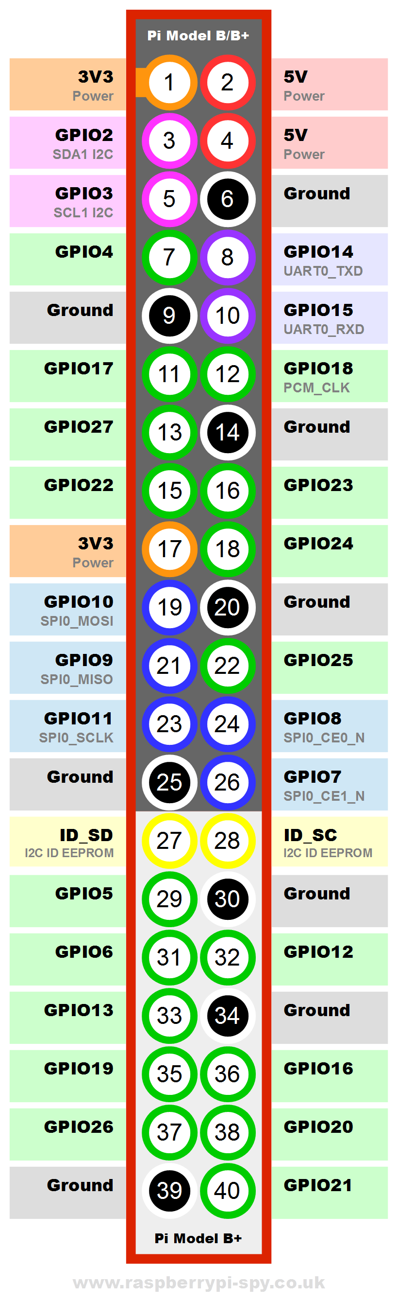
There is no GPIO1(as you can see on this image) but there is a BCM 1 (3v3) 
The BCM numbering is the PIN number (as seen in the circles on this image)
And yet I’ve already proven that using gpio write 1 1 will turn on an output on pin 18. I think you’ve made my point.
Pin 18 is GPIO24.
Does the same thing happen if you write to GPIO24?
(I can’t reach my pi right now)
Hi Bob and Albin,
Bob’s GPIO readall is also what appears on my Raspberry Pi 3 B. The following gpio commands will turn an LED (with 330 ohm resistor) on and off
gpio mode 1 out  //this sets pin #1 (GPIO #18) to output
gpio write 1 1 //this turns pin #1 (GPIO #18) on
It looks like the information to trust is from the gpio readall command. It looks like the pin numbers have changed. This adds an unnecessary layer of complexity.
When using GPIO commands in the terminal, use Pin #1. When programming with Xojo, use GPIO #18.
Pin #1, and GPIO 18 are the same pin.
I just ran a simple LED program and this works on the Raspberry Pi 3 B.
Ok, time for a beer…
(Edit: Whoever thought that having many numbers (a.k.a. GPIO #18 = Pin #1 = physical pin #12) must have been mad)
It was a limitation of keeping the number of layers of the board down to keep the cost down.
That’s interesting Bob. I’ll have to look into this a little more. Thanks for the information 
Perhaps the diagram on this page will help: https://projects.drogon.net/raspberry-pi/wiringpi/pins/
There is no GPIO pin 1. However, wiringPi does some mapping and by default with the command line, pin 1 maps to BCM 18. Personally I’ve only ever used the BCM numbers and that’s what nearly every tutorial I’ve worked with also use. If you setup wiringPi with Xojo by calling the wiringPiSetupGpio method, then you use the BCM numbers.
With the wiringPi GPIO utility command-line app, use the “-g” option to use the GPIO (BCM) pin numbers: https://projects.drogon.net/raspberry-pi/wiringpi/the-gpio-utility/
Ack! Three different methods of numbering pins!
@Eugene Dakin Do your examples use the BCM numbers?
@Bob Keeney , Yes, I use the BCM numbers which are the same number in your picture with the Vilros breakout board.
GPIO 18 = BCM 18 = Xojo 18 = Physical Header Pin #12 = wiringPi Pin #1
Yep … Pin Madness … and even MORE madness. I post this here to help others.
I just spent probably 10 hours or so in the last several days Googling and experimenting. I have an Orange Pi Lite board and I could not get the gpio command to change any pin output. I also have a Pi 3 and that seemed to also not work … until I figured out the crazy pin out values in this thread. Once I figured out I had to use the wPi and BCM columns on on the gpio readall command it all worked on the real Raspberry Pi board.
I also have a CanaKit Breakout board. It looks like it is the same as the picture Bob Keeney posted above and is marked with pin numbers. Pretty handy for testing. But Pin 18 on the board is wPi 1 with the gpio command.
Well … in addition to the problem above, on the Orange Pi Lite, it appears that the header for the 40 pin interface is physically reversed from the Raspberry Pi 3. I had a hint because finally I checked the voltage on the 5V bus on the breakout board and the polarity was reversed. The 3V3 but had some random fraction of a volt.
I flipped the ribbon plug on the Orange Pi Lite side and it all worked. I was able to change the pin output just like the real Raspberry Pi 3 board once the pin number issue was resolved.
The Orange Pi Lite is interesting because it includes WiFi and only costs $12, has 512Mb of RAM, 2 USB ports, and an HDMI port. Physically it is just slightly larger than a Pi Zero. I have tested and it can run a stand alone Web App on the board just fine along with other things like VNC for remote access. That price is from AliExpress in China but the shipping to the USA was only about $5 for the board, case, and power brick (different from a Pi). It seems Amazon has the same board for about $20 and free shipping if you are Prime. The low price is somewhat offset by the lack of documentation.
One other difference on the Orange Pi is the GPIO functions are not loaded by default. I got them from here: https://github.com/zhaolei/WiringOP
They are different than the standard Raspberry Pi version but the gpio command line is the same syntax.
I have yet to try the Xojo GPIO class to see if it works with an Orange Pi Lite. I will post that finding here once I figure that out. Worst case I suppose for slower I/O I could simply shell and use the gpio command line tool. The libwiringPi.so library for the Orange Pi is a slightly different name but it seems to exist. The documentation on the link above seems to indicate it is compatible with the real Raspberry Pi library.
Thanks for those that contributed to this thread.
Whew …
There is a small arrow always on the Orange PI machines that shows first pin so you know which way the orientation is. It varies between Orange PI models which way they face but if going by the arrow your good.
Bjorn … I know better than to assume things but when I saw that the 40 connector was the same as a Raspberry Pi it did not register that it might be reversed.
Thanks for the tip.
My next challenge … hopefully the Orange Pi will work with 1-Wire devices.