Had a working RPi program a few weeks ago. Finally got back to it, did all the updates the Pi had and now my program no longer works with any IO. When I try to toggle a GPIO channel a few times via my app I get this error:
Glib critical source id 130 was not found in attempting to remove it.
I’ve updated the GPIO module form GitHub and everything else I can think of. But my Xojo app no longer drives the GPIO channel. We’ve gone in and verified that the wiring is still good by manually turning the channel on and off.
Any ideas?
Hi Bob,
Minor updates on the Pi do not seem to cause these issues, and when a larger or major update occurs on the Pi then all of the settings are set back to default. Occasionally I have had to reinstall WiringPi, and quite often the I2C program has needed to be reinitialized (sudo raspi-config).
This would be a good place to start.
Thank Eugene. Actually I’ve done both of those. Reinstalled WiringPi and reinitialized I2C.
Hi Bob,
Just a few more issues that it could be. Could you check the following?
- Is there enough free memory space on the Micro SD Card? Sometimes a 32-Gb card is formatted to 1-GB by default
- To check if the GPIO is working, type the command
gpio readall and if the table appears with the name and appropriate voltages (0-volts low, 3.3-volts high, 5-v for 5-volt pins) then the GPIO program would be working.
This will help narrow down the issue. 
- I’m using a 64 GB MicroSD card and have 22.5GB of free space available.
- gpio readall works properly. We have manually turned on and off our SSR using gpio write.
Just to show some code:
In my App.Open I’m calling
GPIO.SetupGPIO
And on my Window, I have a button that I use to toggle the state of the relay:
[code]bRelayState = not bRelayState //Global boolean
dim iOutput as integer
if bRelayState then
iOutput = GPIO.HIGH
else
iOutput = GPIO.LOW
end
GPIO.DigitalWrite(1, iOutput)[/code]
Like I said yesterday, this code worked a couple of weeks ago. So to sure what changed. I have tried with R1.1 and with the latest R2 beta.
I forgot to add that in the Window Open event I initialize the GPIO channel:
 //Setup the output for the Solid State Relay
  GPIO.PinMode(1, GPIO.OUTPUT)
I give up for now. There is something very messed up with my Pi. I’ve simplified, updated, upgraded everything I can think of and the the next thing to do is wipe it and start over. If I’m feeling bored I might try that this afternoon.
I started with a clean Raspbian install and found that one of the mirrors for updates was bad. Once I put a new mirror site the updates and upgrades seem to be doing something different. Will report back once all of it is done. I’m hoping it was just incomplete upgrades.
I hate Linux sometimes.
Well, shoot. I started with a clean OS and still no difference. Installed Raspbian version 8 ‘jessie’. Did the full update and upgrade routines, can manipulate GPIO manually using GPIO commands, etc. I know it’s not a wiring issue as I can set the output manually.
Very frustrating on many levels. I don’t know if it’s a Raspbian, WiringPi, or a Xojo issue. The fact that I had a working application a few weeks (really more like 8 weeks) ago says that it’s a Raspbian issue and something in all those updates broke Xojo. Not even sure where to begin.
Hi Bob,
It is good news that the GPIO can be turned on and off with manual commands, as this saves troubleshooting parts that are working. Here is a download link to Example 5-2 from my book, its a simple LED with a 330-ohm resistor on/off program, and below is the writeup for this example in the Table of Contents from my book.
Example05-02.zip
TOC with Example 5-2 Instructions
Could you give this a go and see if it works? One possible issue is the SetupGPIO command can only be called once, and is usually placed in the Open event. I just tested this example on my Raspberry Pi 3 B with all of the latest updates and it worked on my system.
Thanks for your patience!
Sadly, it’s going to be another couple of weeks before life settles down again to get back into it again.
Bob, are you sure you want to write to Pin 1? That should be the +3.3 V pin on a Raspi 2.
gpio write 1 1 turns on the relay from the command line. Plus, this code worked a month ago.
When doing gpio readall GPIO channel 1 is pin 12 (IIRC).
Pin 12(BCM numbering) is GPIO18(BOARD numbering)
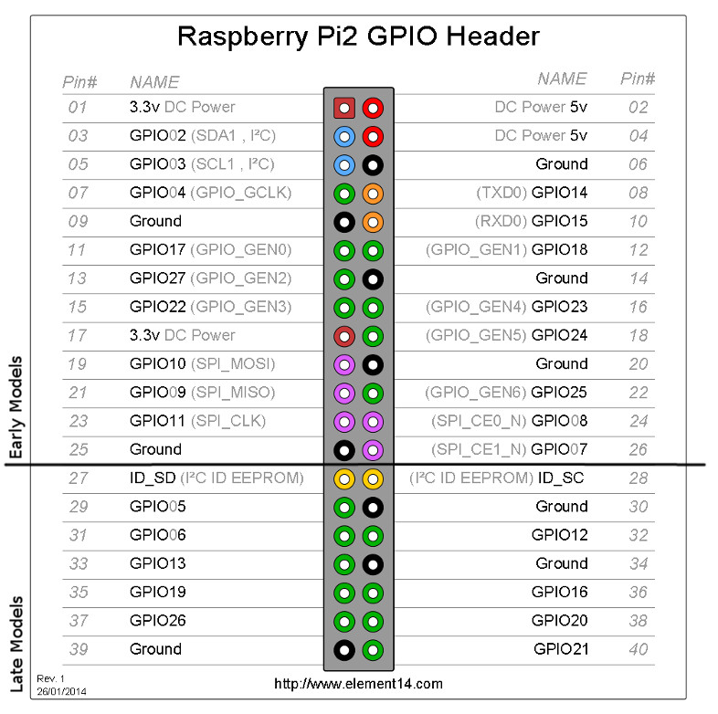
That did it. I swear it worked 6 weeks ago.
As my wife of so helpfully reminded me, “Being a programmer is fun and rewarding, right?”
Have I mentioned that I’m an idiot yet?
…As long as you got it working, that’s all that matters I have had way too many Palm-to-face moments myself!
Have any experience getting thermocouple sensors working?
I have been able to get 1-wire digital thermometers, and built-in temperature sensors working. What type of thermocouple is it?
I missed your previous post about the Max 31855. Is it this amplifier (there are two versions)?:
Max 31855 - version 2.0
It looks like it works with Type-K thermocouples. Does this link point to the one you have?
Type K Thermocouple